Scope of application
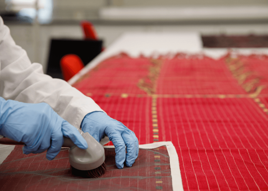
This method provides for testing the breaking strength and elongation of textiles by the grab method or modified grab method. Tests may also be carried out with the sample in the wet state.
The grab method can be used to test woven, woollen or shrink-woven fabrics, whereas the modified grab method is mainly used to test woven fabrics. This method is not recommended for glass fibre fabrics, knitted fabrics or other high-elasticity fabrics (more than 11%). For the determination of breaking strength and elongation of textiles by the selvedge yarn or cut strip method, refer to ASTM D 5035.
The method is available in two units: inch-pound and SI. US customers generally use inch-pound as the unit, while international standards generally use metric SI as the unit. Different units are generally used in different standards. Such different units are not equivalent.
Definitions of terms
- Breaking strength – The maximum force recorded when a specimen is pulled apart, corresponding to the point of rupture, the breaking strength. It is synonymous with the force at the point of fracture. For harder raw materials, the maximum force is generally obtained at the point of rupture. In the case of softer materials, the maximum force may be obtained before fracture.
- Breaking load — generally do not use this name, now generally renamed as the breaking force.
- Constant Rate of Extension (CRE) Tensile Tester – A tester in which the elongation of a sample is consistent with time.
- Constant Rate of Loading Load (CRL) Tensile Testing Machine – the test sample in the first three seconds loaded with the same time of a test machine.
- Constant Rate Traction (CRT) Tensile Tester – A tester that pulls a clamp at a uniform rate and applies a weighting mechanism to the load through the other clamps so that the increase in load or elongation at break is dependent on the elongation characteristics of the sample.
- Breaking Elongation Rate- The amount of elongation of a material as a percentage of the elongation prior to elongation, usually expressed as a percentage.
- Extension – The change in length of a material due to stretching (equivalent to elongation).
- Grab Method- A fabric tensile test in which the central part of the specimen is held in the direction of the width of the specimen.
- For example, the width of the sample is 100mm (4.0in.), and the width of the chuck is 25mm (1.0in.), then the sample centre 25mm is clamped by the clamp, but along the width direction, both sides of the side from the edge of the 37.5mm (1.5in.) outside the part are not clamped.
- Modified Grab Method – On the basis of the grab method of sampling, the long side of the sample in the centre of the two edges of the inward cut by an appropriate proportion, so that the sample is a better-clamped test method. The purpose of such a cut is mainly to prevent the grip method of testing outside the clamping part of the edge of the yarn on the strength of the pulling effect.
- Tensile test – A term used in textiles to describe a test method for determining the tensile-elongation properties, breaking strength and elongation at break of textiles.
For definitions of other terms used in this test method, refer to ASTM D 123.
Test Method
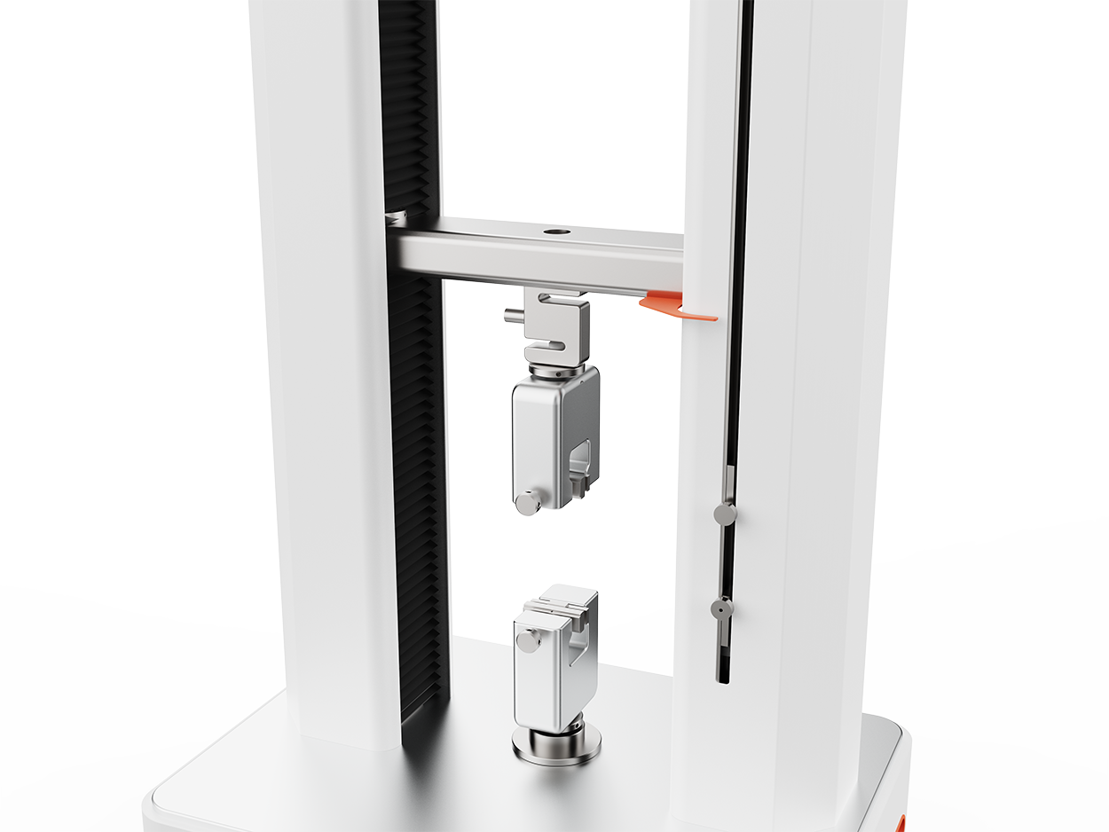
A 100mm (4.0 in.) wide specimen is clamped in the centre of the tensile tester’s jaws and the apparatus is activated until the specimen breaks. The test results (breaking strength and elongation at break) can be read directly from the tester, from the load-extension curve, or by connecting a computer.
This test method uses two kinds of test specimens (G-grip method and MG-modified-grip method) and three alternative test instruments (CRE, CRL, CRT) to describe the grip tension test of fabrics.
Types of Tester
| Test samples | CRE | CRL | CRT |
| Grab Method | G-E | G-L | G-T |
| Modified Grab Method | MG-E | MG-L | MG-T |
Note: E is referred to as a grip test by CRE Tensile Tester.
Purpose and Significance
- The Grab Method has been widely used commercially as an acceptance test for the breaking strength and elongation of most woven or non-woven fabrics. Whereas, the Modified Grab Method is used to test the breaking strength and elongation of most fabrics and is also widely used in commerce. Commercially, once a dispute arises due to different test results, the buyer and seller should do some comparative tests to determine whether there is any statistical bias between the buyer’s and seller’s laboratories, so a recognised statistical method is recommended to assist in checking for bias. At a minimum, both parties should take a set of samples that are as homogeneous as possible and should always be from the same batch of the same type of material. If deviations are found, either the cause of the deviation shall be identified and corrected, or it shall be necessary for the parties to agree to interpret the results of subsequent tests in the light of known deviations.
- This method can determine the dry and wet state of the fabric.
- The strength data obtained with different types of instruments are not comparable. When it is necessary to compare the results of different types of instruments, the instruments should be adjusted as much as possible so that the breaking time is between 20±3 seconds, otherwise, the test results may be very different.
- This method is best performed using an isokinetic elongation system, and in the event of a dispute arising from a difference in test results, 20±3 seconds should be used as the basis for measuring the time of rupture, unless otherwise agreed between the buyer and seller.
- This method also determines the effective strength of the fabric, which means that the breaking strength of the specimen includes the auxiliary strength of the yarns next to the clamping area so that the breaking strength of the fabric is not only a reflection of the strength of the yarns in the clamping area of the specimen. The grab sample method is convenient and quick to take samples, but need more test cloth, due to the different types of structure of the fabric will affect its tensile properties, strip sample method and grab sample method test results can not be converted to each other simply.
- In the strip method, generally need to pull the selvedge yarn after the test, but some fabrics are easy to be further scattered after the force, so the use of the modified grab method is better. This method is suitable for the determination of some fabrics with high strength.
- This method is not recommended for the following angles: Due to the high elasticity of knitted fabrics, it is not recommended to use this method. For fabrics with high strength greater than 200N/cm (11401bs/in), it is recommended to correct some parameters of this method for later testing, but special attention should be paid in the test.
Preparation of specimens
The long side of the specimen is cut parallel to the test direction (warp or weft), if necessary, both directions, in practice, the general direction of the warp and weft need to take samples for testing. Special attention should be paid to the sampling should be taken as far as possible into the diagonal sampling, to ensure that all samples do not contain the same warp or weft yarns. In addition, weft sampling should be separated by a larger distance as far as possible. Warp and weft sampling, as far as possible, to avoid the edge of the cloth and ensure that one-tenth away from the edge of the cloth sampling.
Grab Method
Cut the sample to a width of 100±1mm (4±0.05in.) and a length of at least 150mm (6in.), with the long side parallel to the direction of the test and the direction of the applied force.
The length of the specimen should be determined by the type of clamp used. In addition, the specimen should be long enough to ensure that the ends of the specimen protrude at least 10 mm (0.5 in.) from the clamp head, and the length of the specimen can be calculated in accordance with Equation (1) or Equation (2).
Specimen length (mm) = C + 2W (1)
Specimen length (inch)=K+2W (2)
C—- constant, equal to 95mm. It is the spacing (75mm) plus the protruding length of the clamp ends (20mm).
K—- constant, equal to 4in. It is the spacing (3in.) plus the protruding length of the clamp ends (1in.).
W—- width (mm) of the clamp in the direction of force (in.).
From the long side 37 ± 1mm (1.5 ± 0.02in.) draw a line parallel to the long side (along the direction of the yarn of the fabric), as the clamping specimen mark line.
Modified Grab Method
Cut the specimen according to the above description for the modified grip method.
For very high strength fabric samples are generally taken on the long side of the length of not less than 400mm (16.0in.), and make a good sign line.
Will each sample on both sides along the central cut 2 notches, perpendicular to the test yarn, in addition to those close to the centre of 25 ± 1mm (1.0 ± 0.02in.) of the yarn not apply, on the other yarns effective, see the revised grab sample method specimen diagram.
When the specimen has less than 25 yarns per inch, the cut should be made so that the number of yarns to the nearest 25mm (1in.) (calculated physically) is not cut. The test results shall be adjusted to 25 mm.
When it is necessary to determine the strength under wet conditions in addition to the strength under standard conditions, the test should be performed on twice as many samples. In order to facilitate the comparison of results, generally can first take the long side of the sample length of 2 times the sample, and then divide it into two, half of the standard conditions to do the test under the condition of wet, the other half can be used to determine the strength of the wet state.
When there are specimens in the soaking shrinkage, it must be noted that the wet state of the breaking strength of the sample should be slightly longer than the standard conditions of wetting under the breaking strength of the sample.
Instrument Preparation and Calibration
- The machine shall be prepared in accordance with the manufacturer’s instructions and the conditions of use given.
- Set the effective distance (spacing) between the two clamps to 75±1mm (3.0±0.05in.).
- Select the instrument test range to calibrate the instrument between 10% and 90% of full scale.
- Except in special circumstances, select the instrument test speed of 300 ± 10 mm/min (12 ± 0.5in./ min).
Clamp System
- Check that the clamp surface is flat and that the front and rear clamps are parallel.
- Make a sandwich-style white sheet of paper with two sheets of copy paper placed back-to-back against each other, or with the first sheet folded over the top of the two sheets of copy paper.
- Apply even pressure to the paper in the clamp.
- Remove the paper and check that the indentation of the paper on the white paper is uniform.
- If this indentation is not perfect or does not meet the requirements, the clamp system should be adjusted appropriately and the clamp system should be rechecked with white paper and copy paper.
Note: The main source of irregularities in the clamping system is surface contact and metal surfaces. The main sources of irregularities in the clamp system are surface contact, metal surfaces, or coatings on the clamp surface, and the direction of the applied force.
Calibration of the entire instrument operating system
- The entire operating system (loaded elongation, clamping, recording or data acquisition) is checked by testing the breaking strength and elongation at the break of a standard fabric specimen by the grab method. The values are compared with those of a given standard fabric. It is recommended that the test be carried out at least once a week, and in addition, the whole system should be checked when there is a change in the loading system (especially when the load is increased) or in the clamping mechanism.
- The range of the instrument is selected according to the breaking strength and elongation properties of the standard fabric.
- Prepare test samples of standard fabrics as described in the Test Procedure.
- The clamping pressure is fully checked by placing the specimen on the machine and drawing a marking line along the joint between the machine and the fabric. Break the specimen and observe the movement of the marking line to determine if the clamp is slipping. If slippage occurs, adjust the clamp air cushion pressure during the test or tighten the clamp manually. If an increase in clamp pressure causes the collet to fracture, this should be eliminated by using methods such as padding the clamp or treating the specimen as a corrugated specimen.
- The standard fabric test is carried out in accordance with the Test Procedure.
- The breaking strength and elongation at the break of the standard fabric are calculated and the mean and standard deviation are calculated in accordance with the Test Procedure.
- The data are compared with previous results for the standard fabric and if the differences are outside the permissible range, the system is re-calibrated to find the differences.
Test Procedures
- When placing the specimen, the parallel line drawn closest to the edge of the front (upper) jaws shall be used as the standard, with the fabric oversized out of the jaws as uniform in length as possible. This parallel line ensures that the number of yarns of the same length of fabric is clamped in each collet that the force applied to the fabric in the direction of the test is not at an appropriate angle, and that the tension along the width of the specimen is uniform.
1.1 For very strong fabrics, it is generally difficult to clamp them securely in accordance with the above method. In order to prevent slippage, as shown in Figure 3, an auxiliary steel bar may be added to each end of the specimen and, if required, clamping pads may be used. Clamp the clamp so that the pressure is transmitted along the upper (front) clamping surface of the clamp while taking care not to clamp too tightly, otherwise in the front of the clamp is likely to cause the specimen to break, but the clamp must not be too loose, otherwise it will cause the specimen to slide or in the back of the clamp to cause the specimen to break.
- The elongation at break depends on the initial length of the specimen, which is easily affected by the pre-applied tension on the testing machine. If you need to measure the elongation at the break of the sample, place the specimen on the upper clamp of the machine and apply a uniform tension to it, which should not exceed 0.5% of the full scale.
2.1 In order to achieve a uniform preloaded tension, an auxiliary metal clamping block (6.3) may be preclamped to the underside of the specimen and placed below the lower jaw of the testing machine, and the auxiliary metal clamping block may be removed after the lower jaw has been clamped uniformly.
- A horizontal line may be drawn across the specimen at the intersection of the specimen and the clamp to check for specimen slippage during the test. If the specimen slips, there will be a distance between the line and the clamp.
- Start the instrument and pull off the specimen.
- Record the breaking strength in the warp and weft directions (machine direction and cross direction) and, if necessary, the breaking strength and elongation at the break of the specimen.
5.1 Some instruments are connected to a computer and the data can be read on the computer.
- If a specimen slips, breaks near the jaws, or for any other reason, the data should be discarded if the result is significantly lower than the average result of the specimens, and the test should be resampled and continued to obtain the desired number of average breaking strengths.
Note: Discarding of data shall be based on variations in the specimens themselves and observation of the fracture condition of the specimens. If there are other rules for discard, such as breakage within 5 mm of the chuck or results below 50% of the average, all data should be discarded. Data obtained in other cases should not be discarded unless a problem is identified.

- If fabric slips around the collet or if more than 25% of the specimens break within 5mm (0.25in.) of the collet, the test parameters should be modified according to one of the following principles, and once the modifications have been made, the specifics of the modifications should be noted in the report
7.1 clamp can be added pads.
7.2 The specimen can be coated at the specimen clamping place.
7.3 The clamping surface may be trimmed.
Note: It is generally difficult to accurately analyse the cause of specimen breakage in the vicinity of the clamp. If the specimen breaks due to clamping, this data should be discarded. If the fracture of the specimen in the vicinity of the clamp is due to a random distribution of weaknesses in the specimen, these data should not be discarded. In some cases, the fracture in the vicinity of the clamp is due to the clamping relationship so that when the specimen is stretched, the specimen shrinks in the vicinity of the clamp and the relative pressure increases, thus making it easy to fracture. Fracture in this case is unavoidable and should be a characteristic of this type of test, which often occurs in the grip method of testing.
- The use of the wet state method for testing the breaking strength of specimens with shrinkage should be modified by a formula whereby the number of dry and wet yarns should be based on the condition of the specimen after it has been dried and moistened, with reference to ASTM D 1059.
Calculation of Test Result
Breaking strength—For each laboratory sample and experimental condition, the average value of the force at break, i.e., the maximum value applied to the specimen as read directly from the tester, is calculated for all qualifying specimens.
Determination of Surface Elongation – Unless another force is specified, the elongation generally measured refers to the elongation of the qualified specimen at the breaking strength. The increase in specimen length is tested on the load-tension curve from the starting point to the corresponding specimen breaking strength or other force, as shown on an automatic plotter. The elongation is calculated as a percentage increase in specimen length based on the spacing of the specimens (original length of the specimen).
For qualified specimens, this method calculates the average elongation of the specimen in each case, e.g., the elongation from the breaking force or other force values.
Note: The elongation calculated from the spacing of the specimens should be considered to be the apparent elongation, since the actual length of the fabric is usually greater than the spacing of the specimens. The difference in length is due to the fact that the fabric is pushed out between the grippers. Therefore, there is usually an error in the calculation of the spacer elongation. The magnitude of the error depends on the amount of fabric pull-out.
Correction for breaking strength of specimens in the wet state:
For some reason, the breaking strength of a wet specimen obtained by the grabbing method can be allowed to shrink by applying the following formula to calculate the breaking strength of a wet specimen.
S=(L*C)/W
S—- corrected the value of the breaking strength of the wet state specimen.
L—- breaking strength of the wet state.
C—-number of yarns in the wet state.
W—- number of yarns in the wet state.
If the treatment of the specimen resulted in shrinkage, the breaking strength of the specimen was also corrected when comparing the breaking strength of the fabric before and after wetting.

Causes of Deviations in Accuracy
Some of the most common sources of error and causes of low accuracy in tensile testing are as follows:
Failure to recheck that the tester’s pointer is back to zero after changing loads or ranges.
Pre-tension must be applied to the specimen when it is placed or clamped on the tester, and the presence of pre-tension does not guarantee that every test will start from zero.
One of the most serious problems that many users do not realise is not the faulty clamping mechanism. Many of the calibration procedures for tensile testing machines, whether performed by the manufacturer’s representative or by the user, such as checking spacing, load variability and tensile speed, fail to check the entire operating system including the clamping mechanism.
A standard fabric with a known breaking strength was used to check the entire operating system.