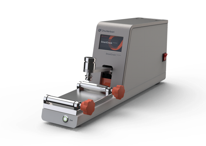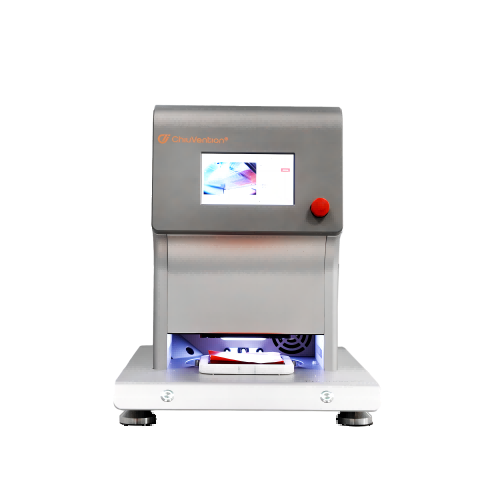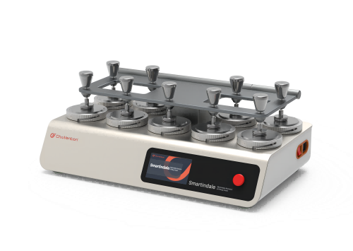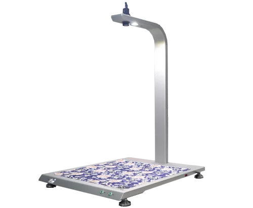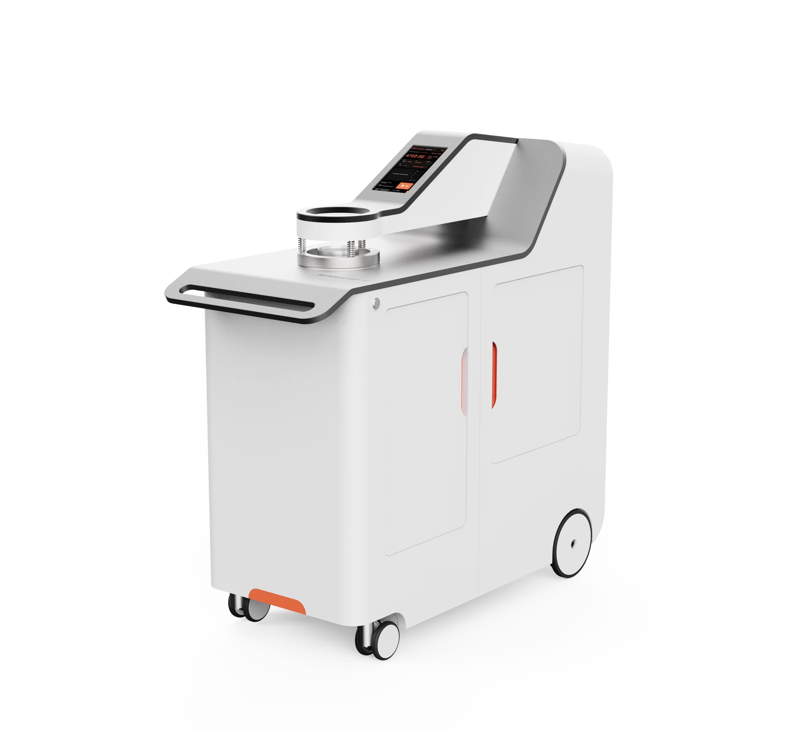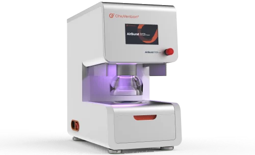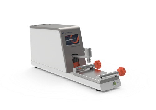
Fully automatic testing, efficient and reliable.
When you load the friction cloth and sample and press start, the friction head will land on the sample. It will then move it back and forth. Then, it will automatically stop and lift up after a set number of times. This reduces the influence of manual operation on the test results. It also makes the test faster and more accurate.
Automatic stretching device for elastic fabrics, more accurate testing
The patented sample clamping and stretching device solves the problem of wrinkles when testing knitted samples: it automatically stretches the samples to the same distance while clamping, avoiding wrinkles or overstretching of the samples and making the test more accurate and reproducible.
Wet and dry friction tests can be performed in a single test, 40% faster.
Only one piece of sample is needed in direction of warp and weft, and through the innovative flexible platform, the dry and wet friction tests can be completed successively on the same piece of cloth, which saves sampling and loading time and greatly speeds up the test by 40%.
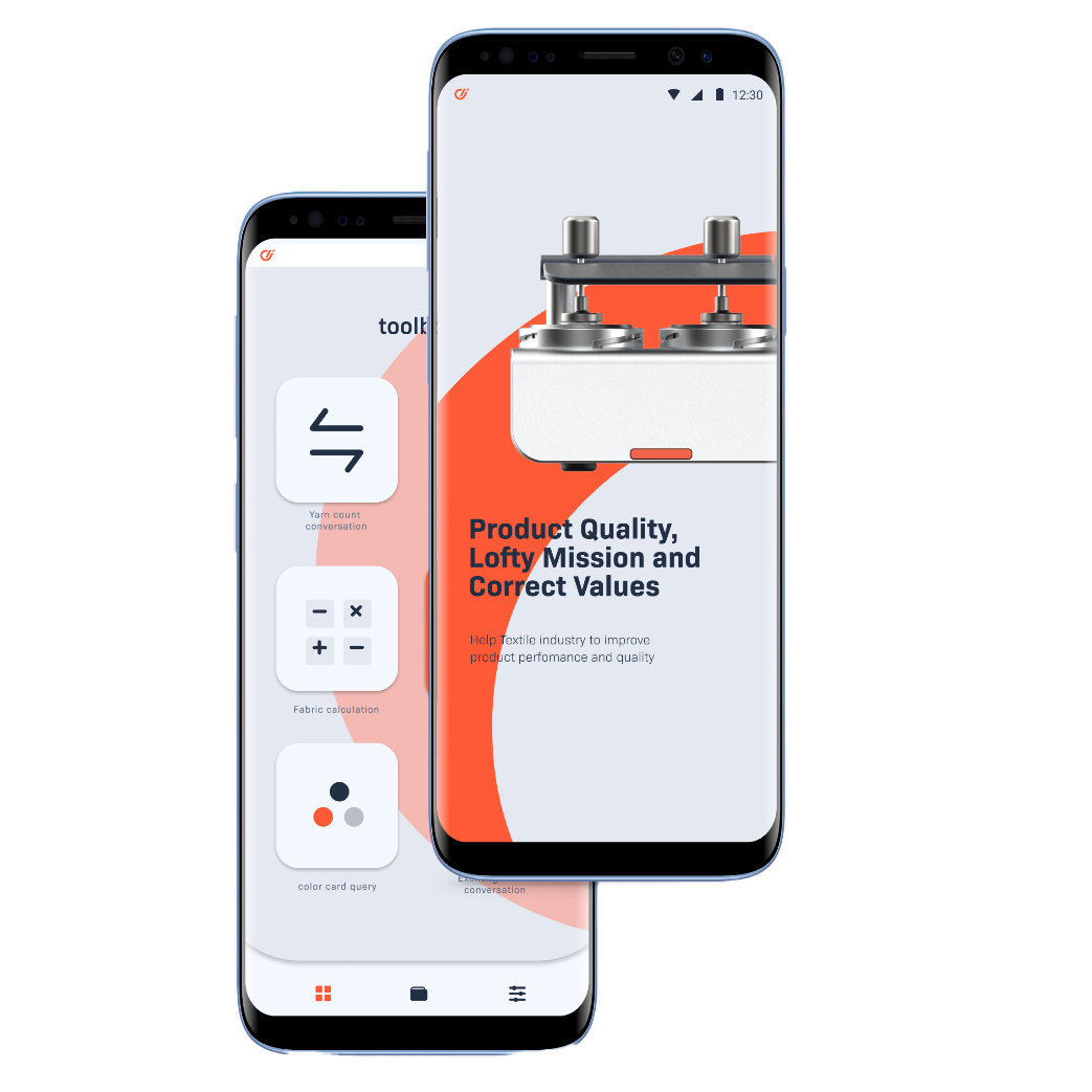
Connected to SmarTexLab, the test results can be uploaded to ERP or LIMS.
The SmartCrock can connect to the SmartTexLab App by ChiuVention Team via Wi-Fi. This allows you to set parameters or track the test from your smart phone. And the test results will be seen in the SmartTexLab, besides, it can be uploaded to the company’s ERP or LIMS. This paperless and intelligent testing makes textile lab quality management easier and faster.
Wet and dry rub tests can be carried out quickly, saving 20% time.
You can hold wet and dry specimens at the same time. The removable loading table lets you quickly switch between the textile’s friction zones. You can perform dry and wet friction tests quickly.
Noiseless and durable.
Moving parts use linear guides. They make the instrument run smoothly and quietly. The main body of the sample table is made of durable aluminum alloy.
Designed in Germany, quality is our life.
All our textile testing instruments are developed in-house and in cooperation with a team of renowned German industrial designers, which makes our instruments of outstanding quality.100% source factory and factory price.
Customer Feedback
“I purchased textile testing instruments from ChiuVention many times. They are good at innovating, such as this Crockmeter, speeds up our testings.”
“I like this design and functions. It runs smoothly and we can input the test results into the smart system, so it is useful for our lab data management.”
OUR BROCHURE
FLYER
Crock Tester Standards
Standard
ISO 105×12 (round friction head), AATCC 8, GB/T 3920 (round friction head), ISO 20433 Method C;
Optional standard
ISO 105xD02, AATCC 165, ISO 105×12 (rectangular friction head), GB/T 3920 (rectangular friction head)
The Specification of Crockmeter
Friction head diameter 16 mm
Vertical pressure 9N +/- 10%
Friction stroke 104 mm
Standard accessories
- AATCC friction cloth
- Sandpaper
- Clamping sleeve
- Sampling plate
Optional accessories and consumables
1.AATCC/ISO Friction Cloths
2.AATCC/ISO stained gray card
3.Sandpaper
4.Rectangular test head with clamping ring
5.Round clamping ring
Power 220 / 110 V 50 / 60 Hz
Weight 23Kg
Dimension 663*173*250 mm (L*W*H)
GET A QUOTE
Frequently Asked Questions
What is a Crock Tester and how does it work?A fabric textile tensile tester is a machine. It measures the strength and stretchiness of fabrics. It works by gripping a strip of cloth or other materials, such as leather, paper, or yarn, on both ends. Then, you pull it until it breaks. Advanced sensors measure the force needed to remove the fabric. They also measure how far it stretches before breaking. This gives quantitative data on the fabric’s tensile properties.
Can it perform both dry and wet crocking tests?The most common testing machine used for tensile testing is the universal testing machine(UTM). It features two crossheads: one is adjusted to accommodate the length of the specimen, while the other is driven to apply tension to the test specimen. These testing machines can be either electromechanical or hydraulic.
For accurate testing, the machine must have appropriate capabilities for the test specimen, including sufficient force capacity, speed, precision, and accuracy. Various accessories, such as grips, extensometers, and temperature chambers, are used to adapt the machine for different materials and testing conditions.
Can the equipment test multiple samples simultaneously?The SmartPull Fabric Textile Tensile Tester weighs 90 kilograms. This is due to its optimized design. So, it’s easier to move and use. This tensile machine uses the latest technology. This includes AC servo motors and precision ball screws. They make force accuracy better. Its improved hardware and software make the testing 20% more reliable.
Is the rubbing pressure adjustable? What is the pressure range?It has an emergency stop button and an overload protection system. It also has travel range limits and warns about abnormal torque or issues. Its ergonomic design reduces injury risks.
What is the material of the rubbing finger? Does it meet the standard requirements?The SmartPull Fabric Textile Tensile Tester software is easy to use. It presents detailed tensile test results. These include elongation, time, greatest force, and modulus. They also include breaking force and more. It allows you to compare past results. You can also export data and create custom tensile strength test reports.
How to calibrate a Tensile Tester ?Preparation
Check the equipment: Before starting the calibration, make sure that there is no physical damage to the Tensile Strength Tester itself, and that the sensors, fixtures, display, and other parts are working properly.
Ensure leveling: The Tensile Strength Tester must be placed on a level workbench to avoid tilting the machine resulting in inaccurate testing. Use a level or the leveling function that comes with the machine to check.
Calibrate the load cell (force transducer)
Selection of standard weights: Select standard weights of known accurate quality. It is usually necessary to use calibration weights that comply with national or international standards. The range of the weights should cover the operating range of the Tensile Strength Tester.
Hanging weights: Hang the weights on the transducer according to the operating manual of the Tensile Strength Tester. Make sure the weights are hung at the correct position and angle to prevent deviations in the test force values.
Record display readings: After loading the weights, observe and record the force values displayed by the Tensile Strength Tester and compare them with the actual force values of the weights.
Adjust the calibration coefficient: If the force value displayed by the Tensile Strength Tester does not match the actual force value of the standard weights, use the calibration function that comes with the machine or adjust the calibration coefficient through the software until the displayed force value is consistent with the weights.
Displacement sensor calibration
Check the zero point of the displacement sensor: without loading any force, check whether the displacement displayed by the Tensile Strength Tester is zero. If there is deviation, reset the zero point of the displacement transducer.
Measure standard displacement: Using a standard calibration fixture, set the tensioner to move a certain distance (e.g., 10 mm, 50 mm, etc.) and then record the displacement reading displayed by the tensioner.
Adjusting Displacement Calibration: Compare the actual displacement with the displacement displayed by the Tensile Strength Tester. If there is a deviation, adjust accordingly according to the equipment manual.
Speed calibration
Set Speed: Set the tensioner to a known travel speed (e.g. 10 mm/min) and start the tensioner.
Use a stopwatch or other measuring tool: Use a stopwatch to measure the actual distance and time traveled by the fixture or fixture beam and calculate the actual speed.
Adjust the speed parameters: If the actual speed does not match the set speed, make adjustments according to the calibration method of the device to ensure the accuracy of the speed setting.
Verify the calibration
After completing the calibration of the load cell, displacement sensor, and speed, perform the following verification steps:
Repeat the calibration process: Load the weights and measure the displacement and velocity again to verify that the calibration is accurate and stable.
Compare reference equipment: If possible, compare tensile test results with other calibrated reference Tensile Strength Testers to ensure consistency.
Adjustment of environmental conditions
When calibrating, make sure that the environmental conditions are consistent with actual use, including temperature and humidity. These conditions can affect the tensile test results, so ensuring the stability of the environment in which the Tensile Strength Tester is located is a critical part of calibration.
What is the replacement frequency and cost of the rubbing fingers?Before using our tensile testing equipment, check the installation guide for environmental needs and machine securing. Connect electricals according to source rating specifications. Initialize when empty and tare the tester. Next, calibrate in ascending and descending order. Use deadweights certified for 20% to 100% of the capacity range. Save calibration results for further use.
Is it manually or electrically operated? If it's electrically operated, is the speed adjustable? What is the speed range?elect matching international test standards based on fabric type. Set suitable grips, jaws, or fixtures. Input the recommended test speed, pre-tension rate, and gauge length as per standard. Specify the allowed elongation percentage without damage. Check if the data recording rate meets the standard. Zero the balance force sensor. Verify the alignment and centering of loaded fabric samples. Start the auto-return on the sample break.
Is it equipped with an accurate counter? What is the precision of the counter?Use pneumatic grips with rubber coating to hold dense, woven fabrics. Use smooth, lightweight mechanical clamps for light, sheer fabrics to avoid damage. Inspect across the width to check the center while loading. Observe the tensioning display to check for slackness or issues. Start a pre-tension cycle to correct minor orientation deviations.
Is the sample fixation device designed for easy operation?If you see variability, recheck the grip pressure settings. Also, replace worn-out jaws. Recalibrate the load cell if accuracy declines beyond the permissible limit. Confirm that you have pre-conditioned the specimen. Verify that mounted gauge length dimensions are accurate. Increase the sample size or test repeats for more statistical confidence. Compare against certified reference equipment. The room temperature and humidity were stable throughout the entire test duration.
Can it accommodate different fabric thicknesses and types?People replace consumable parts. These parts include grips, jaws, load cell mounts, couplings, pulleys, and drive belts. They wear out over time. Calibrated spare sensors and load cells can cut potential downtime. Other recommended spares are fuses, cords, and pneumatic component kits. Their typical replacement frequency varies. The frequency of use determines their usage.
A fabric textile tensile tester is a machine. It measures the strength and stretchiness of fabrics. It works by gripping a strip of cloth or other materials, such as leather, paper, or yarn, on both ends. Then, you pull it until it breaks. Advanced sensors measure the force needed to remove the fabric. They also measure how far it stretches before breaking. This gives quantitative data on the fabric’s tensile properties.
The most common testing machine used for tensile testing is the universal testing machine(UTM). It features two crossheads: one is adjusted to accommodate the length of the specimen, while the other is driven to apply tension to the test specimen. These testing machines can be either electromechanical or hydraulic.
For accurate testing, the machine must have appropriate capabilities for the test specimen, including sufficient force capacity, speed, precision, and accuracy. Various accessories, such as grips, extensometers, and temperature chambers, are used to adapt the machine for different materials and testing conditions.
The SmartPull Fabric Textile Tensile Tester weighs 90 kilograms. This is due to its optimized design. So, it’s easier to move and use. This tensile machine uses the latest technology. This includes AC servo motors and precision ball screws. They make force accuracy better. Its improved hardware and software make the testing 20% more reliable.
It has an emergency stop button and an overload protection system. It also has travel range limits and warns about abnormal torque or issues. Its ergonomic design reduces injury risks.
The SmartPull Fabric Textile Tensile Tester software is easy to use. It presents detailed tensile test results. These include elongation, time, greatest force, and modulus. They also include breaking force and more. It allows you to compare past results. You can also export data and create custom tensile strength test reports.
Preparation
Check the equipment: Before starting the calibration, make sure that there is no physical damage to the Tensile Strength Tester itself, and that the sensors, fixtures, display, and other parts are working properly.
Ensure leveling: The Tensile Strength Tester must be placed on a level workbench to avoid tilting the machine resulting in inaccurate testing. Use a level or the leveling function that comes with the machine to check.
Calibrate the load cell (force transducer)
Selection of standard weights: Select standard weights of known accurate quality. It is usually necessary to use calibration weights that comply with national or international standards. The range of the weights should cover the operating range of the Tensile Strength Tester.
Hanging weights: Hang the weights on the transducer according to the operating manual of the Tensile Strength Tester. Make sure the weights are hung at the correct position and angle to prevent deviations in the test force values.
Record display readings: After loading the weights, observe and record the force values displayed by the Tensile Strength Tester and compare them with the actual force values of the weights.
Adjust the calibration coefficient: If the force value displayed by the Tensile Strength Tester does not match the actual force value of the standard weights, use the calibration function that comes with the machine or adjust the calibration coefficient through the software until the displayed force value is consistent with the weights.
Displacement sensor calibration
Check the zero point of the displacement sensor: without loading any force, check whether the displacement displayed by the Tensile Strength Tester is zero. If there is deviation, reset the zero point of the displacement transducer.
Measure standard displacement: Using a standard calibration fixture, set the tensioner to move a certain distance (e.g., 10 mm, 50 mm, etc.) and then record the displacement reading displayed by the tensioner.
Adjusting Displacement Calibration: Compare the actual displacement with the displacement displayed by the Tensile Strength Tester. If there is a deviation, adjust accordingly according to the equipment manual.
Speed calibration
Set Speed: Set the tensioner to a known travel speed (e.g. 10 mm/min) and start the tensioner.
Use a stopwatch or other measuring tool: Use a stopwatch to measure the actual distance and time traveled by the fixture or fixture beam and calculate the actual speed.
Adjust the speed parameters: If the actual speed does not match the set speed, make adjustments according to the calibration method of the device to ensure the accuracy of the speed setting.
Verify the calibration
After completing the calibration of the load cell, displacement sensor, and speed, perform the following verification steps:
Repeat the calibration process: Load the weights and measure the displacement and velocity again to verify that the calibration is accurate and stable.
Compare reference equipment: If possible, compare tensile test results with other calibrated reference Tensile Strength Testers to ensure consistency.
Adjustment of environmental conditions
When calibrating, make sure that the environmental conditions are consistent with actual use, including temperature and humidity. These conditions can affect the tensile test results, so ensuring the stability of the environment in which the Tensile Strength Tester is located is a critical part of calibration.
Before using our tensile testing equipment, check the installation guide for environmental needs and machine securing. Connect electricals according to source rating specifications. Initialize when empty and tare the tester. Next, calibrate in ascending and descending order. Use deadweights certified for 20% to 100% of the capacity range. Save calibration results for further use.
elect matching international test standards based on fabric type. Set suitable grips, jaws, or fixtures. Input the recommended test speed, pre-tension rate, and gauge length as per standard. Specify the allowed elongation percentage without damage. Check if the data recording rate meets the standard. Zero the balance force sensor. Verify the alignment and centering of loaded fabric samples. Start the auto-return on the sample break.
Use pneumatic grips with rubber coating to hold dense, woven fabrics. Use smooth, lightweight mechanical clamps for light, sheer fabrics to avoid damage. Inspect across the width to check the center while loading. Observe the tensioning display to check for slackness or issues. Start a pre-tension cycle to correct minor orientation deviations.
If you see variability, recheck the grip pressure settings. Also, replace worn-out jaws. Recalibrate the load cell if accuracy declines beyond the permissible limit. Confirm that you have pre-conditioned the specimen. Verify that mounted gauge length dimensions are accurate. Increase the sample size or test repeats for more statistical confidence. Compare against certified reference equipment. The room temperature and humidity were stable throughout the entire test duration.
People replace consumable parts. These parts include grips, jaws, load cell mounts, couplings, pulleys, and drive belts. They wear out over time. Calibrated spare sensors and load cells can cut potential downtime. Other recommended spares are fuses, cords, and pneumatic component kits. Their typical replacement frequency varies. The frequency of use determines their usage.